Frequently Asked Questions
Troubleshooting
There are a number of reasons why a Uhing drive can slip. These are the four most common reasons:
1) The wrong kind of lubricant has been used. Never use oil, silicone, WD-40, graphite or another lubricant that reduces friction.
2) The load (for example a wire guide roller) is too heavy or it has been mounted in such a way that it is placing overturning moments of force on the Uhing drive.
3) The four screws used to mount the load to the top of the Uhing drive are too long.
4) The Uhing drive is very old (more than 10 years) and the bearings are worn down.
Used properly, a Uhing drive will not slip. Please contact Amacoil if your Uhing drive is slipping.
 Chances are you have a Uhing model RG drive and are rotating the shaft in the wrong direction. The RG drive operates with the shaft rotating in one direction ONLY. Reversal is mechanically controlled with a special mechanism on the drive unit. Reversing the shaft with a model RG drive will cause the drive to stop at the end of its stroke and create undue wear on the bearings. The Uhing model RS drive does require shaft reversal in order to change travel direction.
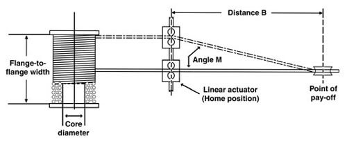
Could be that your traverse unit is so old the bearings need to be replaced. Thrust requirements are at a maximum at the end of each stroke. Worn bearings could cause the skipping. We’ve had units sent back to us after ten years of 24×7 use, and the bearings hardly look worn. Other times we see a unit that’s been in service for only a few years and the bearings are completely worn. This can mean the traverse unit size is not properly matched to the application requirements. Not only the diameter and line tension of the material you are winding, but also the physical set up of your winding assembly, go into determining the exact size of the Uhing traverse drive nut needed. For example, if angle “M” in the illustration below is too great, it can cause a drive that’s too small to skip or even stall.
The best solution to your problem is to phone an Amacoil applications engineer and go over the specifics of your set-up. The next best solution is to go to https://www.amacoil.com/html/form1.htm and complete the winding assembly applications form. After you submit the form online, an Amacoil applications engineer will get back to you to discuss what might be causing your Uhing traverse unit to skip.
General
Uhing drive units have zero backlash whereas backlash is inherent in ball screw systems. Backlash is caused by clearance or “play” between contacting surfaces in ball screws, gears, belt drives and other linear motion devices.
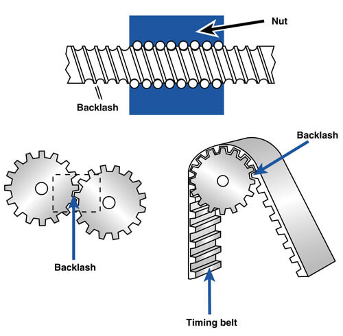
To overcome backlash, ball screw users typically preload the nut to keep the balls under steady pressure. Other methods for fighting backlash include active cam mechanisms, shims and other devices which load the geartrain. These methods can be expensive and their performance level deteriorates over time due to wear and tear.
In a rolling ring drive, there is continuous point-contact between the bearing surface and the shaft. There is no “play” and zero backlash – even during reversal. Additionally, rolling ring drives have built-in overload protection. If the system is overloaded, the nut will slip, not jam.
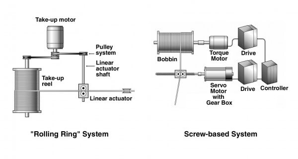
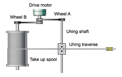
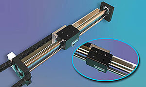
As shown in these illustrations, a rolling ring linear actuator will simplify winding system design, set-up and operation. A rolling ring system eliminates the need for additional motors and controls saving time and money.
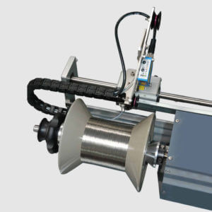
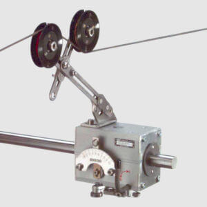 The Guide System attaches to the RG linear actuator to increase efficiency in winding operations. The material being spooled is fed through guide wheels which keep the material in alignment with the take-up spool assuring smooth, even take-up. The GS is easy to install with no special maintenance required.
Technical
If you’re using a large Uhing drive then you might realize 15 feet of travel. The longer the travel distance for a Uhing drive, the thicker the shaft must be to compensate for shaft sag. And the thicker the shaft, the more powerful the drive.
This is fine for heavy, robust applications requiring a lot of side thrust. But a Uhing drive may not be practical for an application with a long travel stroke and a very low thrust requirement. A long stroke requires a thick shaft which means the Uhing drive will have a lot of side thrust. This means you end up with a very powerful unit when all that is needed is a very light duty unit.
Contact Amacoil to see if a Uhing drive is right for your application.
The model RG drive is not rated for shaft rotation. If your application requirements cause the Uhing drive to travel faster than 9.8 in/sec, the reversal mechanism may malfunction. If the Uhing RG drive reverses more than once every two seconds the same problem may occur. Conversely, if the application requires the Uhing drive shaft to rotate less than 10 RPMs, the same problem may occur. Correcting these problems is often a matter of finding the right combination of pitch setting and drive motor speed.
Yes but not often. If the pitch is larger than the diameter of the wire being spooled, there will be spaces between the rows on the spool. If the pitch is less than the wire diameter, the rows will overlap on the spool. Sometimes people want spaces or overlapping but for the vast majority of Uhing users the maximum pitch is equal to the maximum width of the wire or other material being spooled.
In a basic Uhing set up, the Uhing shaft is driven via a belt & pulley system linking the Uhing shaft to the take up spool shaft. The gear ratio refers to the size relationship of the pulley wheels in this linkage. If the wheels are the same size (1:1) then the drive’s maximum pitch will be as listed in the brochure. If the gear ratio is greater than 1, the pulley wheel on the Uhing shaft will be larger than the wheel on the spool shaft and the Uhing shaft will turn slower than the spool shaft. If the gear ratio is less than 1, the pulley wheel of the Uhing shaft will be smaller than the wheel on the spool shaft and the Uhing shaft will rotate faster than the spool shaft. Correct gear ratio and shaft speed is required in order to assure that the linear movement of the Uhing drive stays in synch with the rotation of the spool.
 In a Uhing drive assembly, the L dimension is the distance between the outside edge of one end support to the outside edge of the opposite end support. The L dimension determines how much travel is possible in a Uhing assembly. The converse is also true — the amount of travel desired will determine the L dimension. The L dimension is important because the mounting holes used to anchor the Uhing assembly are located in the bottom of the end supports.
Yes but it’s not the ideal set-up. When a Uhing assembly is placed in its side, the bearings are subjected to different forces than when the assembly is upright. This could reduce the thrust capacity of the drive causing it to skip or causing the bearings to wear down faster. If a Uhing assembly is installed sideways, then a linear slide load carrier is recommended to counter torque and other overturning moments.
For each revolution of the shaft, a rolling ring drive travels a set distance. This distance is the linear pitch of the drive. The Amacoil RG drive offers infinitely variable pitch. The RS drive is a fixed pitch model offering five different pitch settings. Linear speed is the distance traveled per unit of time. For example, five feet per second. Amacoil/Uhing rolling ring assemblies offer linear speeds of up to 13 ft./sec. over a maximum distance of 16 feet.
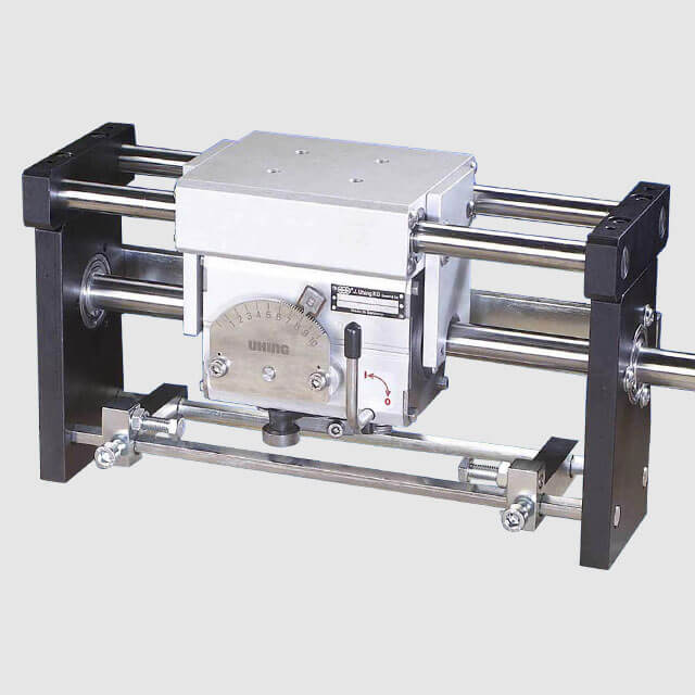
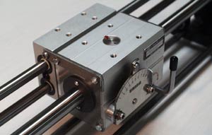
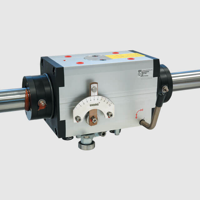
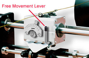 Rolling ring linear drives have a thrust set screw preset at the factory. It applies pressure (preload) to the rolling ring bearings so they maintain constant contact with the drive shaft. This assures accurate thrust and prevents backlash. When the free movement lever is actuated 90° (manually or pneumatically), the thrust set screw pressure is released and the linear drive is easily pushed, in either direction, to any location along the shaft. This eliminates the need to start-and-stop, or “jog,” the system to position the linear drive.
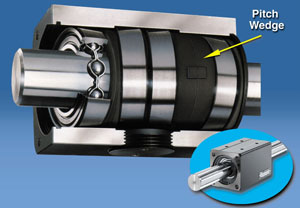 We don’t recommend it. Pitch is factory-set by inserting a series of poly-based pitch wedges between the rolling ring bearings inside the drive nut. The pitch wedges determine the unit’s pitch by holding the rolling ring bearing assembly at a precise angle relative to the drive shaft.
Changing the pitch is an inexpensive (less than $60) process whereby the pitch wedges are switched out for a different set. No other components of the linear motion system need be changed as opposed to other types of linear motion systems where changing pitch can require the purchase of major new parts such as screws, gearboxes and clutches.
The RS comes standard with a fixed pitch setting of 0.5 times the shaft diameter. (The model RS4-25, for example, runs on a 25 mm drive shaft and has a fixed pitch setting of 12.5 mm per shaft revolution.) Each RS drive is now also available with four other pitch settings – 0.1, 0.2, 0.3 and 0.4 times he shaft diameter.
For the Uhing drive to function properly, the linear slide load carrier must follow specified design criteria. The method of attaching the linear bearing slide must be flexible. That is – it must allow the Uhing drive to “float.” There cannot be a rigid attachment between the Uhing drive and the slide or the Uhing drive can seize. Additionally, if you construct a linear slide load carrier yourself, the guide rails must be perfectly parallel to the Uhing drive shaft.
 Uhing drives are designed to provide side thrust only. If any other forces are imposed on the drive – such as weight or overturning moments – then a linear slide load carrier is needed. The linear slide transfers the forces to a separate support assembly. In an assembly model number a linear slide is usually designated as SLS.
They are one in the same. In the model number of a Uhing drive assembly the slowdown cam is designated as “V.” The V-cam is a device which reduces the linear speed of a Uhing model RG drive at the reversal points. If the drive is moving faster than 0.25 meters per second (9.8 inches per second) then the V-cam is needed in order to assure that the automatic reversal lever functions properly.
Applications
 Yes.The FA-II Flange Detection System is easy to use, eliminates the need for an operator to adjust the reversal stops on the Uhing traverse and allows you to use spools of any width. The FA-II system employs a laser sensor mounted to the traverse. When the sensor detects the spool flange, a signal is sent to a pneumatic cylinder which reverses the traverse.To install an FA system on an existing Amacoil set-up, you should consult an Amacoil applications engineer.
 For each different material being spooled, the linear drive moving the wire guide back and forth, must travel a specific linear distance per one revolution of the shaft. This is the pitch of the system. Proper pitch adjustment ensures that material is laid onto the spool in evenly spaced rows.
To assure that a single spooling system accommodates as many different gauge materials as possible, the system must be designed around application requirements for winding the largest size material (see Figure 1). Additionally, planning around the largest spool (flange-to-flange width) is necessary to make certain the system will meet varying axial thrust requirements.
Designing around the largest diameter material – requiring the maximum linear actuator pitch setting — ensures that there is enough “turn down” adjustment available to accommodate the winding of smaller gauge materials. Turning down the pitch on a linear actuator is much simpler and less expensive than, say, changing the motor speed or changing gears to properly wind smaller gauge materials.
Likewise, by designing around the requirements using the widest reel (flange-to-flange), when the linear drive reaches the reel flange, the angle (M) between the point of payoff and the material guide is at a maximum (see Figure 2). The resulting line tension imposes the maximum axial thrust requirement on the linear drive. Narrower reels may then be used on the same system without concern over exceeding axial thrust requirements. (Note: This is true only if distance B remains the same.)
The farther away your point of pay-off is from the linear traverse, the better. In the illustration below, angle M will increase as distance B decreases. As angle M gets bigger, there is a greater chance of your ribbon twisting or folding which would make for a sloppy take-up. By moving the linear traverse farther away from the pay-off you decrease angle M and minimize the risk of twisting the material. Another solution is a “moving spool” set up. To discuss moving spool design please call Amacoil.
 To use the RS drive in a CMM (coordinate measuring machine) application, you need to incorporate a linear scale with the drive. Amacoil provides a pre-integrated assembly which precisely monitors both linear position and travel direction. The unit provides smooth, vibration-free movement with no backlash. Resolution may be specified for either 0.0004 inches (0.01 mm) or 0.004 inches (0.1 mm). The RS-Linear Scale Assembly operates on a smooth shaft at rotational speeds of up to 8,000 rpm. Linear travel speed is up to 4 ft./sec. with axial thrust up to 202 lbs.
 Is there any space behind the traverse unit? If so, you can mount an Amacoil L4 linear slide to the back of your drive nut. The L4 adds only about 1.0 mm in vertical height to your drive assembly, yet completely removes the load from the nut. All radial forces and moments of torque created by overhung or off-center loads are directed away from the drive nut and assembly, and you are assured your system is protected from torque-induced damage.
 Not really. Particulate contaminates rarely find a way into an Amacoil/Uhing rolling ring linear drive. Bellows assemblies are excellent protection against particulate contaminates but they can be expensive to design and build, and they often pose stacking space problems. A better, far less costly solution to meet your concern is to install “scrapers” in the shaft apertures on the linear drive. The scrapers effectively clean off any debris from the drive shaft. Scrapers are available with grease fittings for lubrication of the linear drive shaft.
Maintenance
No. Silicone forms a layer between the shaft and the inner race of the rolling ring bearings and this causes the Uhing drive to slip. The only lubricant that should be used on a Uhing assembly is one which can be squeezed out from between contacting metal parts. The bearings must be able to “bite” the shaft without interference. Use commercially available ball bearing grease that is free of molybdenum disulfide (MoS2 -Free) and graphite.
Once per week, unless rigorous operating conditions make more frequent lubrication necessary. These conditions include long “dwell” times, extremely dirty or dusty environments, and hot (+80°C) environments. Use commercially available ball bearing grease that is free of molybdenum disulfide (MoS2 -Free). Apply by cleaning the shaft and using a rag to spread the grease thinly and evenly. Using a brush or oil can, apply 90W oil to the reversal mechanism. Be sure to oil the spring coils, insertion points and center ring carrier. For a list of maintenance materials suppliers, contact Amacoil toll free: 1-800-252-2645.