How It Works – RG Linear Drive
Rolling Ring Linear Motion Converts Rotary Motion Input into Linear Output and Enables a Variable Speed, Bidirectional Linear Motion System Without Clutches, Cams or Gears
With the Uhing model RG rolling ring linear drive, travel direction and linear speed are both controlled by purely mechanical means. A variable speed linear motion system using an RG drive does not usually require programming or electronic controls. Here’s how it’s done.
Specially Machined Bearings Contact Shaft
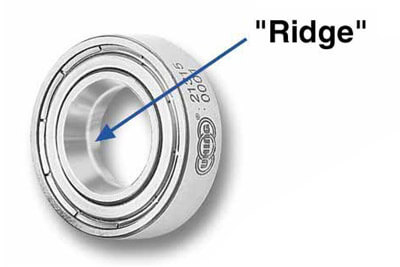
 The inner race of a rolling ring bearing is machined to form a sort of “ridge” which runs around the entire inner race of the bearing. When mounted on a shaft, the bearing contacts the shaft at a single point on this ridge. The bearing may then be pivoted left or right on the shaft and still maintain point contact with the shaft.
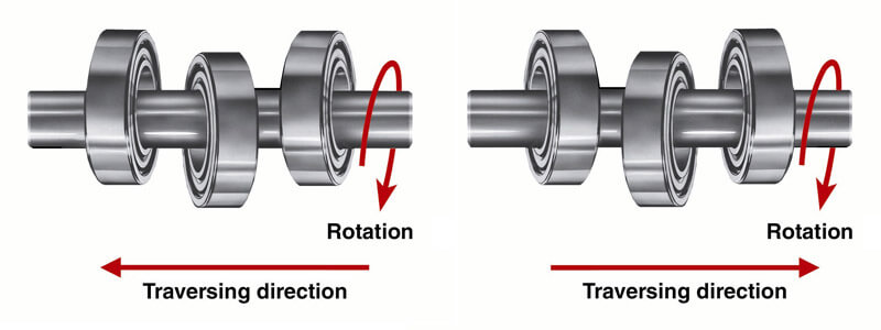
In a rolling ring linear drive, three or four rolling ring bearings are housed inside the nut. When the nut is placed on a smooth shaft, and the shaft is rotated, compression is generated against the bearings’ inner races. This causes the bearings to roll along the length of the shaft. A payload attached to the nut is thereby moved linearly.
Pivoting the bearings changes their angle relative to the shaft. This angle determines the linear pitch and travel direction of the rolling ring drive.
Automatic Reversal
The shaft does not need to be reversed to change the travel direction of the drive unit. When the drive unit reaches the end of the stroke, a mechanical stop triggers the reversal mechanism which pivots the bearings and reverses the drive.

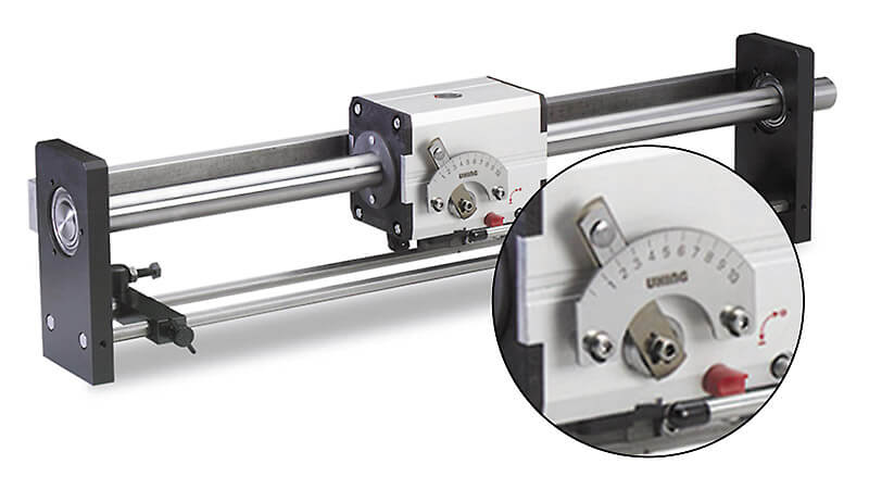
Pitch Control Lever Permits Adjustments to Linear Pitch
This purely mechanical control over direction and pitch makes it simpler to meet application requirements when compared to systems that require clutches, brakes, gearboxes, servo motors and complex control systems. It also minimizes operating and maintenance costs.

Rolling ring drives are supplied as stand alone units or on a shaft in a framework ready to be mounted in manufacturing equipment. Adjustable end stops enable control of stroke length.
